

Transforming 3D models (Photoshop Extended)
After you open a 3D model you can change the model’s position, camera view, lighting, or render mode, create a cross-section view, or play animation contained in the 3D file. To create these changes, you use the Photoshop 3D tools.
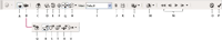
- A.
- Activate 3D object editing tools (C - H)
- B.
- Activate 3D camera editing tools (Q - V)
- C.
- Return to initial object position
- D.
- Rotate
- E.
- Roll
- F.
- Drag
- G.
- Slide
- H.
- Scale
- I.
- View menu
- J.
- Delete current view
- K.
- Save current camera location as a view
- L.
- Lighting and render mode options
- M.
- 3D cross-section options
- N.
- Animation playback controls
- O.
- Cancel current 3D transform
- P.
- Commit current 3D transform
- Q.
- Return to initial camera position
- R.
- Orbit
- S.
- Roll
- T.
- Pan
- U.
- Walk
- V.
- Zoom
 Use the 3D tools
 Do one of the following:
-
In the Layers palette, double-click the 3D layer thumbnail.
-
Choose Layer > 3D Layers > Transform 3D Model.
The options bar changes to show the 3D tools. To leave 3D transform mode, click Cancel 3D Transform or Commit 3D Transform in the options bar.
Move, rotate, or scale a 3D model
 For
tooltips on each 3D tool, choose Palette Options from the Info Palette’s options
menu and select Show Tool Hints. Click a tool, then move the cursor
into the image window to view tool details in the Info Palette.
For
tooltips on each 3D tool, choose Palette Options from the Info Palette’s options
menu and select Show Tool Hints. Click a tool, then move the cursor
into the image window to view tool details in the Info Palette.- Click a navigation tool to activate it:
Hold down Shift as you drag to constrain
the Rotate, Drag, Slide or Scale tool to a single direction of movement.
- Rotate
- Drag up or down to rotate the model around its x‑axis, or side to side to rotate it around its y‑axis. Hold down Ctrl (Windows) or Option (Mac OS) as you drag to roll the model.
- Roll
- Drag side to side to rotate the model around its z‑axis.
- Drag
- Drag side to side to move the model horizontally, or up or down to move it vertically. Hold down Ctrl (Windows) or Option (Mac OS) as you drag to move in the x/z direction.
- Slide
- Drag side to side to move the model horizontally, or up or down to move it closer or farther away. Hold down Ctrl (Windows) or Option (Mac OS) as you drag to move in the x/y direction.
- Scale
- Drag up or down to scale the model larger or smaller. Hold down Ctrl (Windows) or Option (Mac OS) as you drag to scale in the z direction.
Click the Return to default view icon in the Options bar to return the model to its initial view.
To view or edit the numeric x, y, and z position, rotation, or scaling of the 3D model, click the arrow to the right of the 3D tools.
Edit the 3D camera
For tooltips on each 3D tool, choose Palette Options
from the Info Palette’s options menu and select Show Tool Hints.
Click a tool, then move the cursor into the image window to view
tool details in the Info Palette.- Click a camera editing tool to activate it.
Hold down Shift as you drag to constrain
the Orbit, Pan, or Walk tools to a single direction of movement.
- Orbit
- Drag to orbit the camera in the x or y direction. Hold down Ctrl (Windows) or Option (Mac OS) as you drag to roll the camera.
- Roll
- Drag to roll the camera.
- Pan
- Drag to pan the camera in the x or y direction. Hold down Ctrl (Windows) or Option (Mac OS) as you drag to pan in the x or z direction.
- Walk
- Drag to walk the camera (z translation and y rotation). Hold down Ctrl (Windows) or Option (Mac OS) as you drag to walk in the z/x direction (z translation and x rotation).
- Zoom
- Drag to change the field of view of the 3D camera. Maximum field of view is 180.
To view or edit the numeric values for the x, y, and z position, rotation or field of view of the 3D camera, click the arrow to the right of the Edit Camera tools to open the 3D Camera Settings.
Select Orthographic View to display the model in accurate scale view without any perspective distortion.
Change or create 3D camera views
Do one of the following:-
Select a preset camera view of the model from the View menu.
-
To add a custom view, place the 3D camera in the desired position using the Edit Camera tools, then click Save in the options bar.
To return to the default camera view
of the model, click the Return to default camera icon in the options
bar while the Edit Camera tools are selected.Change lighting effects
You can apply different lighting effects to a 3D model such as daylight, interior light or colored light, or remove lighting entirely to create a silhouette effect. The default lighting setting, Lights from File, displays the 3D model using the lighting settings from the original file (created in a 3D authoring program).
Click the Lighting and Appearance Settings icon
and select a lighting mode from the pop‑up palette. Change rendering effects
The default render mode is solid. Modes such as wireframe, outline, or vertice reveal the underlying structure of the model’s components. You can combine wireframe and solid rendering (Solid Wireframe mode), or adjust the transparency of solid areas in the model (Transparent or Transparent Wireframe).
Render modes such as Solid Outline and Line Illustration allow you to adjust the number of structural lines that appear in the model by adjusting the Crease Threshold setting. A crease or line, is formed when two polygons in a model come together at a particular angle. If edges meet at an angle below the Crease Threshold setting (0‑180), the line they form is removed. At a setting of 0, the entire wireframe is displayed.
View cross sections
You can view a cross-section of a 3D model by intersecting it with an invisible plane that slices through the model at any angle and displays content only on one side of the plane.
- In the Cross Section Settings area, select Enable Cross
Section and choose options for alignment, position, and orientation.
- Alignment
- Select an axis (x, y, or z) for the intersecting plane. The plane is perpendicular to the selected axis.
- Position and Orientation
- Use Offset to shift the plane along its axis, without changing its tilt. At a default offset of 0, the plane intersects the 3D model at its midpoint. At maximum positive or negative offsets, the plane moves beyond any intersection with the model. Use Tilt settings to rotate the plane up to 3600 in either of its possible tilt directions. For a particular axis, the tilt settings will rotate the plane along the other two axes. For example, a plane aligned to the y‑axis can be rotated around the x‑axis (Tilt 1) or the z‑axis (Tilt 2).
- Flip
-
Changes the displayed area of the model to the opposite
side of the intersecting plane.
To combine
two rendering modes on a model, duplicate the 3D layer, then change
the render mode on the duplicated layer. Set the cross section to
the same position on each layer, then flip one cross section.
View 3D animations
If a 3D file contains animation, it is included with the file when Photoshop opens the 3D model. To view animations, you use the animation controls in the options bar.
- Choose Layer > 3D Layers > Transform 3D Model.
- Do one of the following:
-
Click playback buttons to play the animation, rewind it, or advance forward or backwards by frame.
-
Click the arrow next to the playback buttons to open the slider control, then drag the slider forward or backwards to move through the animation.
-